So you want to have your MikroTik router rebooted every day at 6 a.m. in the morning before the business start to prevent possible random issues from happening?
Go to MikroTik Winbox, open a New Terminal and enter this one line simple command:
Some of the most requested topics folks ask me for are multi-WAN and load balancing implementations. Unfortunately, as easy as most solutions are on MikroTik, these aren’t simple. Many vendors like Ubiquiti have wizards that you can use during the initial device setup to configure multi-WAN and load balancing, but that hasn’t come to RouterOS yet. Those wizard-based implementations are still complex, but that complexity is hidden from the device administrators.
Using a load balanced multi-WAN setup helps us meet a few design goals:
Failover in case of ISP failure
Increase total available bandwidth for users
Distribute bandwidth utilization across providers
Something that should be noted before you go further – this is a fairly complex topic. Multi-WAN and load balancing requires us to configure multiple gateways and default routes, connection and router mark Mangle rules, and multiple outbound NAT rules. If you aren’t familiar with MikroTik firewalls, routing, and NAT then it might be best to put this off until you’ve had some time to revisit those topics.
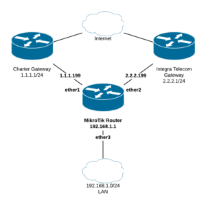
A single MikroTik router is connected to two ISPs (Charter and Integra Telecom) on ether1 and ether2 respectively, and a LAN on ether3. Traffic from the LAN will be NAT’d out both WAN ports and load balanced. See the topology below:
At this point you could stop configuring the router and things would work just fine in a failover situation. Should one of the two providers go down the other would be used. However there is no load-balancing, and this is strictly a failover-only solution. Most organizations wouldn’t want to pay for a second circuit only to have it used just when the first goes down.
Input Output Marking
One problem with having more than one WAN is that packets coming in one WAN interface might go out the other. This could cause issues, and may break VPN-based networks. We want packets that belong to the same connection to go in and out the same WAN port. Should one provider go down the connections across that port would die, then get re-established over the other WAN. Mark connections coming in the router on each WAN:
This helps the router keep track of what port each connection came in from.
Now we’ll use the connection mark just created for packets coming IN to trigger a routing mark. This routing mark will be used later on in a route that tells a connection which provider’s port to go OUT.
Connections that have been marked then get a routing mark so the router can route the way we want. In the next step we’ll have the router send packets in the connections with those marks out the corresponding WAN interface.
LAN Route Marking
Some special Mangle rules are needed to tell the router to load balance headed across the router from the LAN. How this load balancing works is beyond the scope of this article, but suffice to say a lot of hashing happens. If you want to learn more check out the MikroTik documentation.
These rules tell the router to balance traffic coming in ether3 (LAN), heading to any non-local (!local) address over the Internet. We grab the traffic in the pre-routing chain, so we can redirect it to the WAN port that we want based on the routing mark.
The following commands balance ether3 LAN traffic across two groups:
NOTE: The routing marks above are the same in this step as they were in the previous step, and correspond with the routes we’re about to create.
Special Default Routes
At this point we’ve marked connections coming in the WANs, and used those connection marks to create routing marks. LAN load balancing steps above also create routing marks, and they correspond with what the next step does. Create default routes that grab traffic with the routing marks we created above:
Note: These routes only get applied with a matching routing mark. Unmarked packets use the other default route rule created during router setup.
Routes that came in the Charter connection get a connection mark. That connection mark triggers a routing mark. The routing mark matches the mark in the route above, and the return packet goes out the interface it came in.
Summary
Here’s what we’ve configured:
New connections inbound on a WAN get marked
Connections with that mark get a routing mark
LAN traffic heading outbound gets load balanced with the same routing marks
Routing marks match default gateway routes and head out that interface
Down and dirty version. The command line version is below the Winbox instructions. Let’s say you have a DVR that has a static IP of 192.168.1.200, and you need to forward port 3999.
In Winbox
1) Go to IP -> Firewall -> NAT (Figure 1-1).
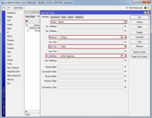
2) Click the “+” to add a new NAT rule. Modify the “Chain” to “dstnat”, “Protocol” to “tcp”, and “Dst. Port” to “3999”. Set the “In. Interface” to your WAN port. (Note: You are telling the router that any traffic coming IN from the Internet on port 3999 should follow this rule. If you forget this step, the router will grab ANY traffic on port 3999 and send it to the IP you specify in the next step) (Figure 1-2).
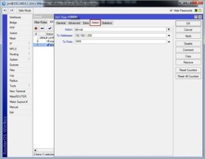
3) Click the “Action” tab, change the “Action” value to “dst-nat”, the “To Addresses” to “192.168.1.200” and “To Ports” to “3999” (Figure 1-3).
Terminal Version
Type the following value into a Terminal window to enter this port forwarding rule.
ISD ofron suport IT me staf të kualifikuar të gatshëm 24×7. Suporti ynë është i disponueshëm online, offline, remote, offsite dhe përmes manualeve të përdorimit dhe të administrimit. Suporti i ISD ofrohet në forma të ndryshme: të herëpashershëm, me kontratë të thjeshtë dhe me kontratë profesionale.