Migration From SQL Server To Oracle Using SQL Developer
Migration is the process of copying the schema objects and data from a non-Oracle database, such as MySQL, Microsoft SQL Server, Sybase Adaptive Server, Microsoft Access, or IBM DB2, to an Oracle database.
To migrate a third-party database to Oracle easily, you can choose the following options using SQL Developer:
– Migrating using the Migration Wizard
– Copying tables to Oracle
Migrating Using the Migration Wizard
The Migration wizard provides a screen to manage all the steps needed for the migration to Oracle database. These steps are as follows:
– Capturing the source database (MySQL, Microsoft SQL Server, Sybase Adaptive Server, Microsoft Access, IBM DB2),
– Converting it to Oracle format,
– Generating DDL,
– Performing the conversion.
After a brief explanation about the process of migration, let’s do a simple migration from SQL Server database to Oracle database.
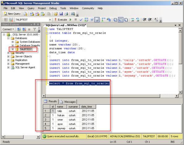
1- I created sample SQL Server database named TALIPTEST.
2- The migration repository is a collection of schema objects that SQL Developer uses to manage metadata for migrations. For a migration repository create a database connection to convenient Oracle database and give following grants.
CREATE USER MIGRATIONS IDENTIFIED BY “migration”
DEFAULT TABLESPACE USERS
TEMPORARY TABLESPACE TEMP;
grant create session to migrations;
grant resource to migrations;
grant create view to migrations;
For multischema migrations, you must grant the privileges with the ADMIN option as follows.
grant resource to migrations with admin option;
grant create role to migrations with admin option;
grant alter any trigger to migrations with admin option;
grant create user to migrations with admin option;
3- Download SQL Developer from http://www.oracle.com/technetwork/developer-tools/sql-developer/downloads/index.html
4- Unzip the file named sqldeveloper-3.2.20.09.87.zip and extract it. Open sqldeveloper.exe file to open SQL Developer.
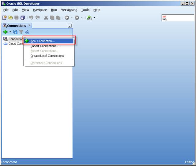
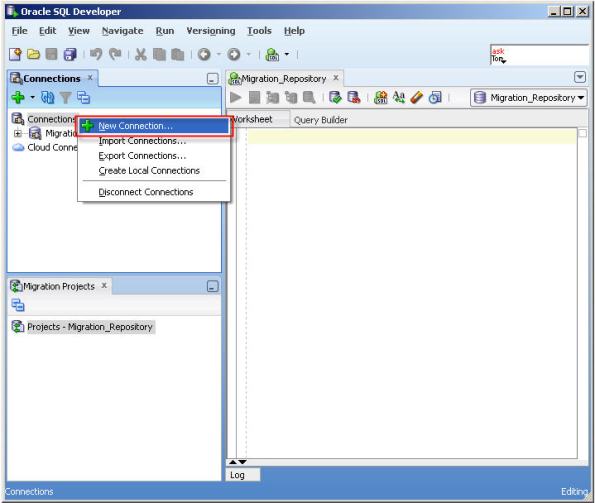
5- Right click to the “Connections” and click the “New Connections”
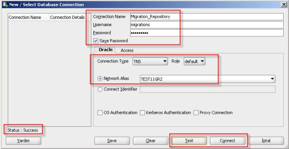
6- Create a database connection named Migration_Repository that connects to the MIGRATIONS user.
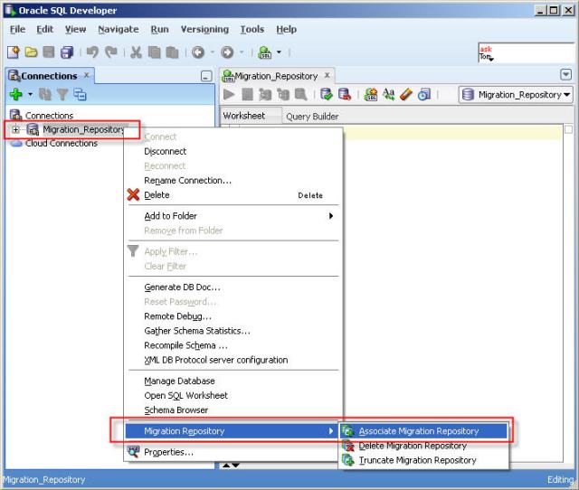
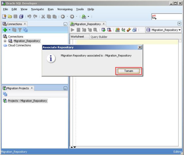
7- Right-click the Migration_Repository connection, and select “Migration Repository” menu , then “Associate Migration Repository” to create the repository.
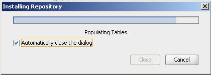
8- Schema objects needed for migration will be created in MIGRATIONS schema.
9- To connect to third-party database (MySQL, Microsoft SQL Server, Sybase Adaptive Server, Microsoft Access, IBM DB2) using SQL Developer, we need jTDS driver. You can download needed jTDS driver from following link. http://sourceforge.net/projects/jtds/files/jtds/1.2/jtds-1.2-dist.zip/download . Extract the dowloaded zip file named jtds-1.2-dist.zip
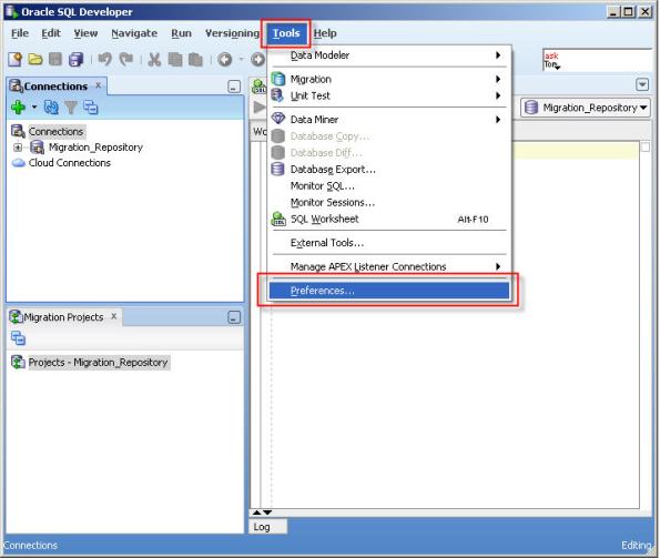
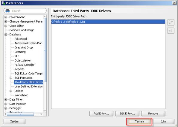
10- Click “Tools” and then “Prefenrences”.
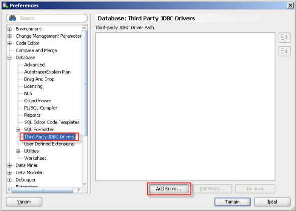
11- Select “Third Party JDBC Drivers” and click “Add Entry” button to add jTDS driver for SQL Server.
12- Select jar file located in jTDS driver folder.
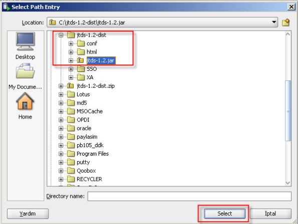
13- Click “OK” button.
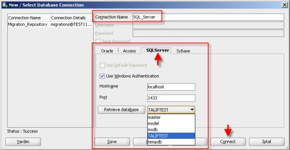
14- Now you can connect to SQL Server or Sybase database using SQL Developer. Connect to the SQL Server database as follows.
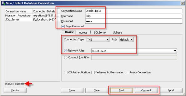
15- And finally, let us create the database connection which we will migrate to.
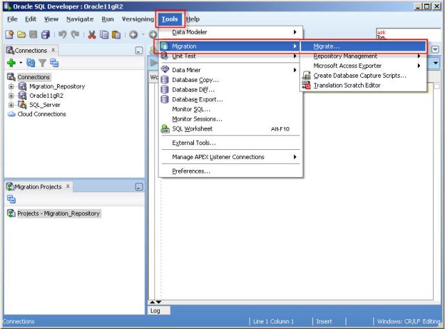
16- The migration wizard is invoked in a variety of contexts. You can right-click a third-party database connection and select “Migrate to Oracle” or you can click “Tools>Migration>Migrate…”.
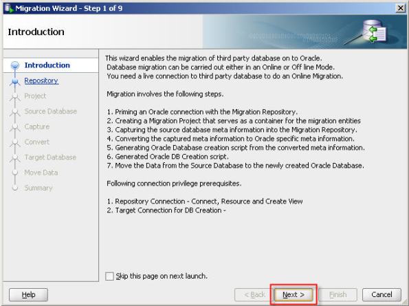
17- Click “Next” button.
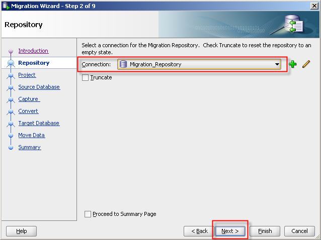
18- Select migration repository database connection.
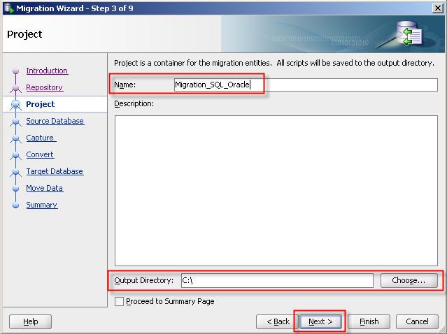
19- Give a name for migration project and select a directory to write output.
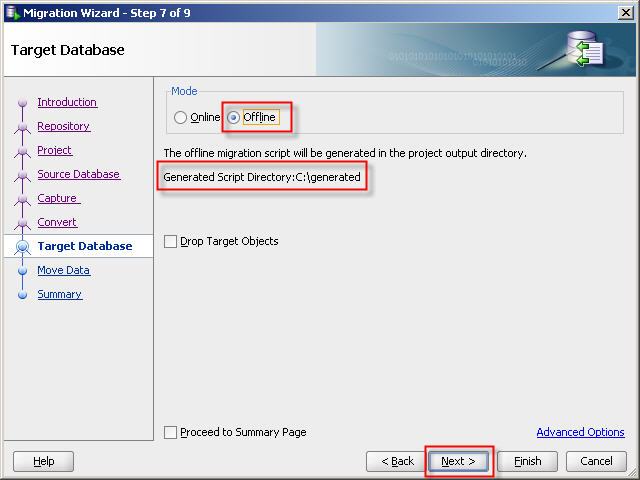
20– Select third party database connection. You can migrate database on online or offline mode. If you choose online migration then Migration Wizard will perform all needed operations. If you choose offline migration then Migration Wizard will generate all needed DDL scripts.
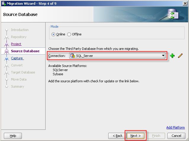
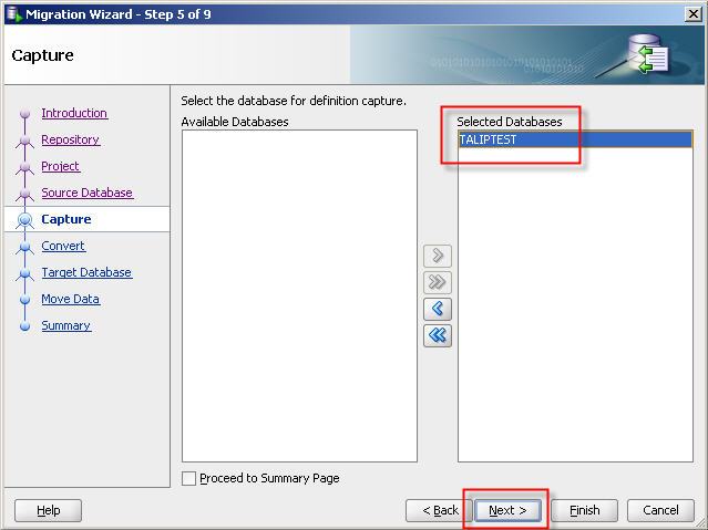
21- Select SQL Server database which we want to migrate to Oracle.
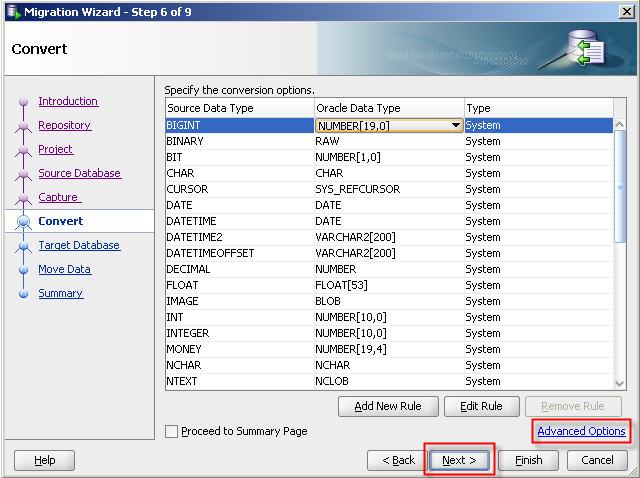
22- Specify the conversion options. And click “Advanced Options” link to ensure “Microsoft SQL Server : Is quoted identifier on” option is selected.

23- Select target database connection.
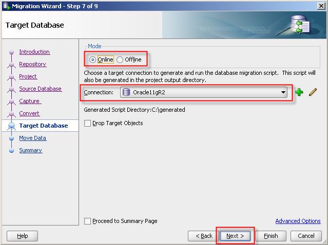
24- If you select offline migration then offline migration script will be generated in the project output directory.
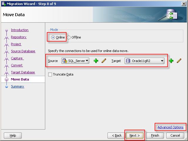
25- Select the connections to be used for online data move.
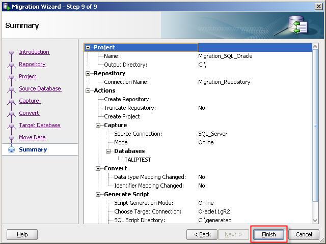
26- Click “Finish” button so start migration.
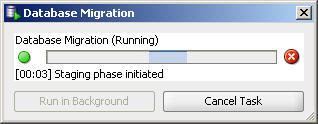
27- Migration and conversion process will be perfomed as follows.
Now, Our SQL Server database in Oracle 🙂
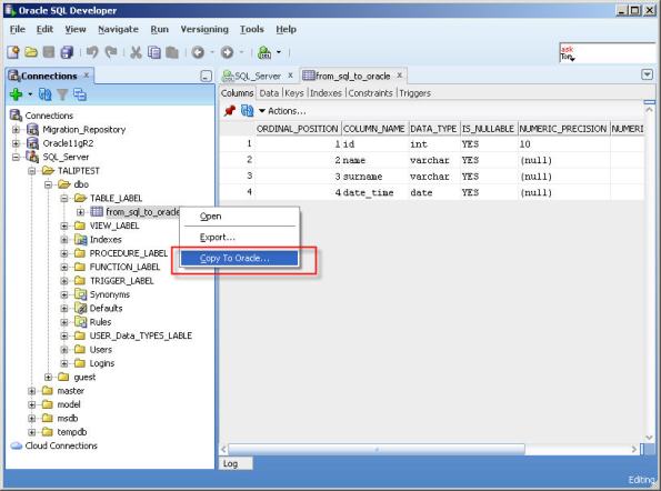
Copying tables to Oracle
Right click the table located in third party database and click “Copy To Oracle”
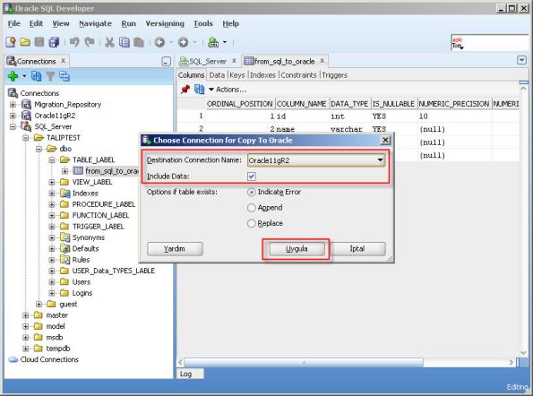
Select destination (Oracle) database connection and click “Apply” button. If you choose “Include Data” check box it will create table structure and move data.
Copy to Oracle database is finished.
Note: This method doesn’t move indexes, triggers, etc. It only moves table structure and data.